Carbon capture technologies
Technical overview of the five main carbon capture methods (their integration constraints, industry fits, and commercial readiness) with a solution provider snapshot.
Deciding which carbon capture technology to use for an industrial facility is complicated. We have standardised technology readiness levels (TRL) 1 to help us evaluate the maturity and commercial viability of each technology (Kearns2025, pp.7), but plant managers also need to consider their own operational specifics (like excess heat output, power grid needs, and supply chain) to assess the feasibility and risks of a given solution as a whole. So, a general technical understanding of how these technologies work is also needed to get a performant capture facility up and running, while interfacing correctly with adjoining carbon transport and storage infrastructure.
Capture methods
Carbon capture technologies recover CO₂ from point sources or directly from the atmosphere turning it into a concentrated CO₂ stream which can be transported to permanent storage or processing facilities for utilisation in other industrial processes. Depending on perspective, there are five main carbon capture methods: post-combustion, pre-combustion, oxyfuel combustion, chemical looping combustion, and direct air capture, each with their own technological variations.
Post-combustion
With post-combustion carbon capture methods, you remove CO₂ from the flue gas 2 after the fuel has been combusted with air. Absorption 3 (solvent-based) is the most mature removal technology (Danish Energy Agency2024, pp.22), though adsorption (solid-based), membranes, and cryogenic separation are progressing with promising results. Overall these technologies are highly versatile because they can be retrofitted onto existing exhaust stacks in facilities like coal plants, cement kilns, waste-to-energy plants, and steel mills without major operational changes.
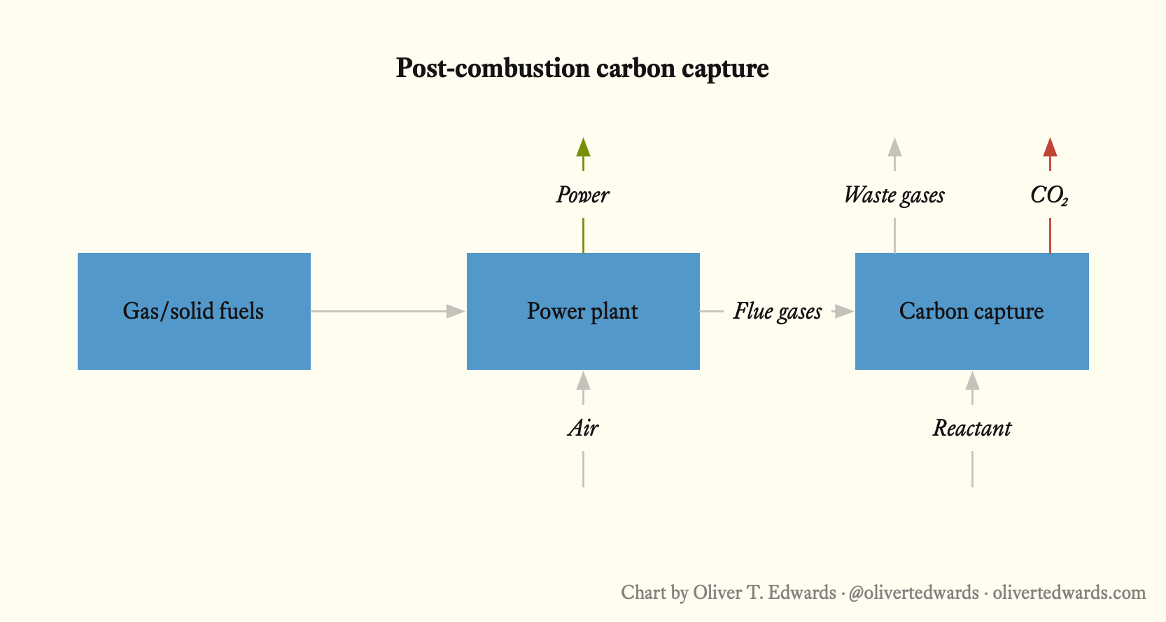
Absorption technologies use amine solvents to scrub CO₂ from the flue gas, followed by thermal regeneration to produce a pure CO₂ stream. With the ability to capture >90% of CO₂, you can retrofit this technology onto nearly any point source with an exhaust gas. It has also been used for decades within the food and beverage industry for CO₂ recovery, and it can also be integrated with steam cycles or district heating to boost efficiency since it requires large amounts of heat. Efficiencies can also be gained from integrating excess heat from combined heat and power plants. Current research focuses on optimising energy use and developing alternative solvents like amino acid salts or ionic liquids.
Adsorption technologies, unlike absorption, use solids like carbon, zeolites, or metal-organic frameworks (MOFs) with amine functional groups to adsorb CO₂ at low temperatures, or calcium looping with lime-based sorbents at high temperatures (600-900°C). Low-temperature processes are often limited by low cyclic loading, rapid sorbent deactivation, and scaling difficulties, while high-temperature calcium looping requires heavy boiler integration, making it unsuitable for retrofits but viable for cement kilns where spent sorbent can be reused. Current research focuses on improving sorbent durability and process scalability, limiting their near-term applicability for retrofit projects.
Membrane technologies separate CO₂ from a flue gas like a sieve. Yet, flue gases are often at low pressure, so we need additional compression or vacuum systems to efficiently drive CO₂ through the membrane leading to increased electricity consumption. Membrane technologies are also sensitive to dust and other pollutants in the flue gas. The technology looks promising at pilot-scale, but with low TRL and limited scalability at this point, they are best suited for high-pressure applications than typical post-combustion scenarios, requiring further development to increase efficiency and robustness for broader industrial use.
Cryogenic separation technologies capture CO₂ by cooling flue gas to very low temperatures (below -100°C) to freeze out CO₂, often requiring compression to avoid extreme chilling. This energy-intensive process faces challenges with handling flue gas pollutants and the high cost of compression and refrigeration equipment. Currently at low TRL, with only small-scale pilot trials conducted, cryogenic separation shows potential but is not yet practical for widespread post-combustion applications. Its development lags behind other technologies, and significant advancements are needed to improve energy efficiency and economic feasibility for industrial deployment.
Potassium carbonate technologies mirror amine-based systems, using a caustic solvent circulated between absorber and desorber columns to capture CO₂ from flue gas. Widely used in chemical industries for gas sweetening, it absorbs CO₂ at higher pressures (1-15 bar) and releases it through pressure reduction and heating. Slower absorption rates require larger equipment, mitigated by flue gas compression or chemical/enzymatic promoters. Variants include fully electrified processes, steam-electrification hybrids, or enzymatically catalysed systems using hot water. Energy consumption is comparable to amine systems, but its flexibility with power or hot water inputs allows cost optimisation. Environmentally benign, PC avoids harmful emissions, but its TRL is lower, with pilot and demonstration projects ongoing.
Chilled ammonia is a proprietary technology using ammonium carbonate instead of amine solvents to capture CO₂, operating at low temperatures to minimise ammonia slip. It promises lower heat consumption and delivers CO₂ at higher pressures (5-25 bar) without amine-related emissions. However, slow absorption kinetics, complex process design, and issues with carbonate precipitation have increased heat demands beyond initial expectations. Demonstrated at a 100,000 tpa scale, it suits concentrated CO₂ sources but faces challenges in broader applications. Its complexity and operational drawbacks make it less competitive than amine systems, though it remains a viable alternative for specific industrial settings.
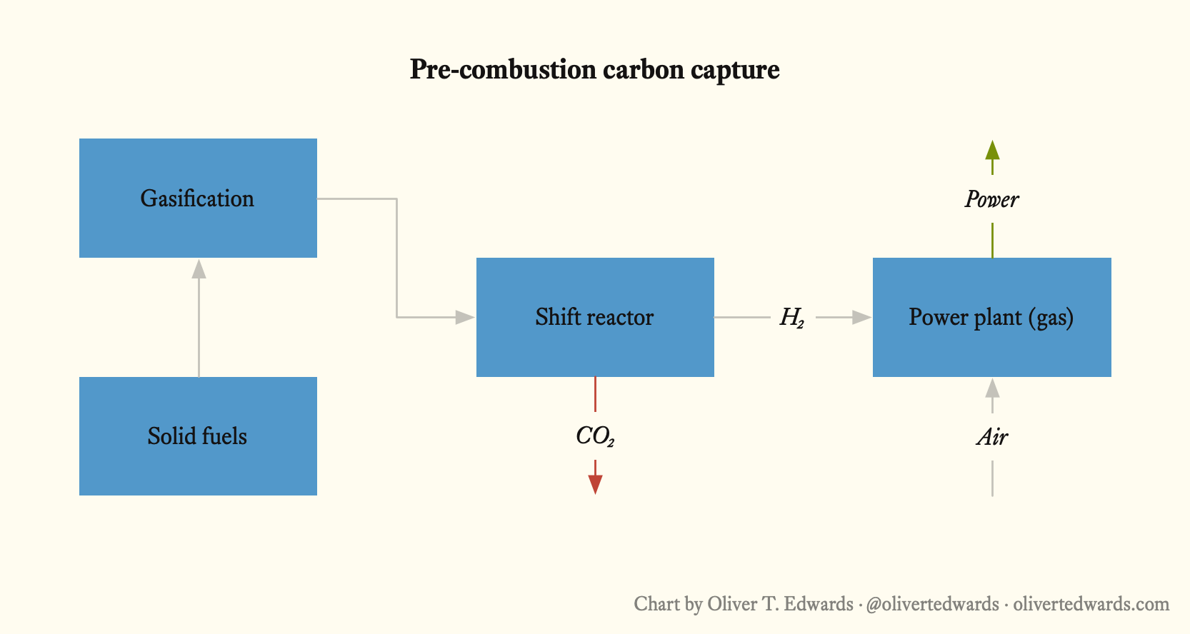
Pre-combustion
With pre-combustion carbon capture methods, you take a fuel like coal, natural gas, or biomass, break it down into syngas (a mixture of hydrogen and CO₂) using heat and steam or oxygen, then remove the CO₂ before burning or using the hydrogen (Danish Energy Agency2024, pp.26). The syngas stream is usually at high-pressure, so capturing CO₂ is easiest with pressure swing adsorption (PSA) 4 (using solid sorbents) or less reactive chemicals (like amine solvents). This technology is mainly used in the fertiliser industry producing ammonia from hydrogen, but it can also be used in the plastics industry or to produce hydrogen from natural gas to be used as a clean fuel. The name pre-combustion comes from its early use in power plants, but it can be misleading since the process doesn’t always involve combustion such as when producing hydrogen as an ammonia feedstock. Despite being an energy-intensive and complex system to setup, it can be built into new power plants designed around gasification.
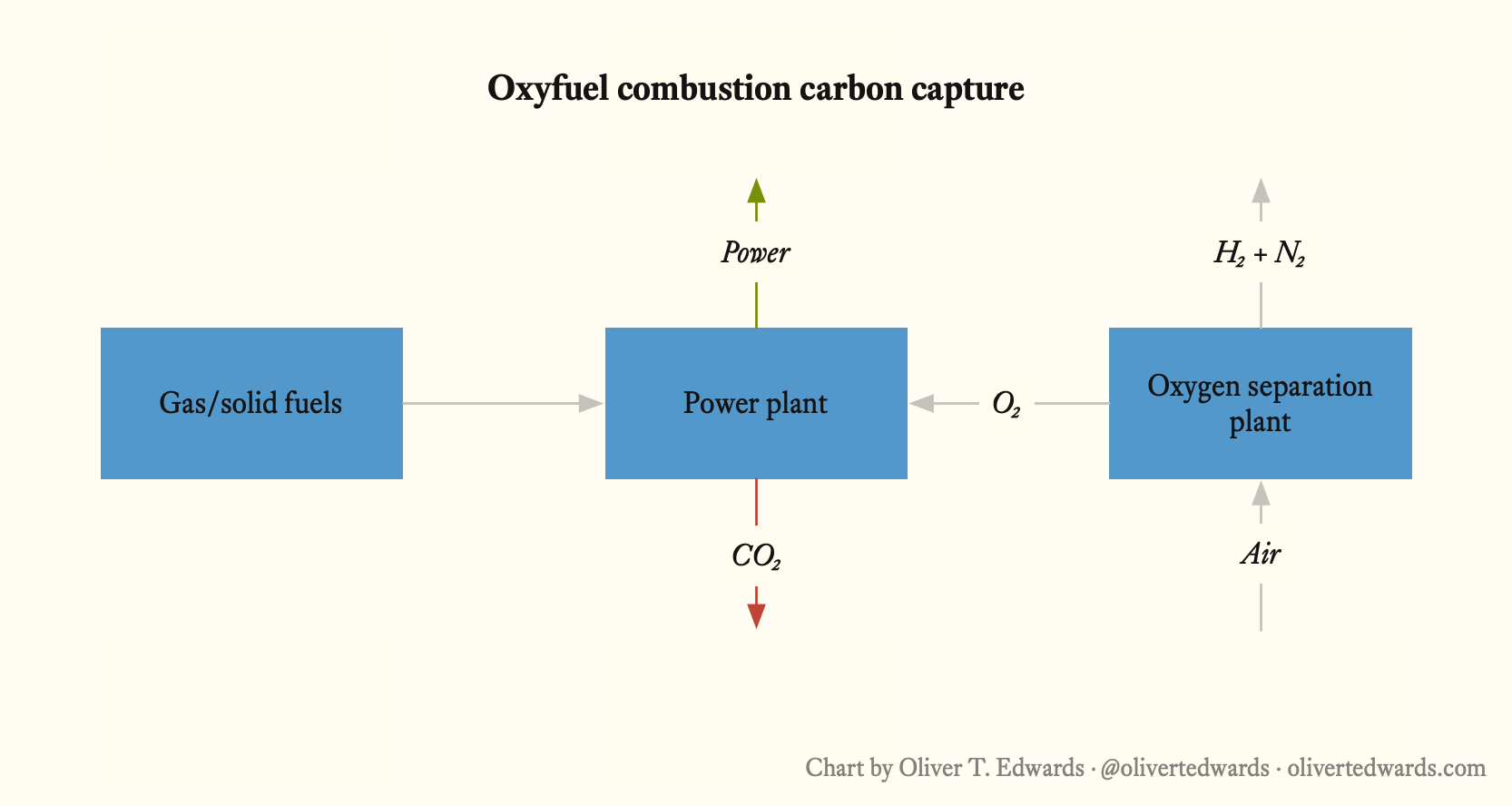
Oxyfuel combustion
With oxyfuel combustion carbon capture methods, you burn a fuel with concentrated oxygen instead of open air to produce a flue gas stripped of nitrogen, consisting mostly of CO₂ and water vapour making separation a lot easier (Danish Energy Agency2024, pp.25) with post-combustion methods. Oxygen separation units produce the pure oxygen, and to keep combustion temperatures manageable, 60-70% of the cooled flue gas is recirculated. After condensing out the water, you’re left with a high-concentration CO₂ stream (70-85% purity) that needs minimal purification and compression. Typical candidates for this capture method is power plants, modified cement kilns, or industrial furnaces, though most implementations require significant modifications to existing facilities. Despite removing nitrogen for a simplified capture process, producing pure oxygen is energy-intensive which can turn this method into a poor investment.
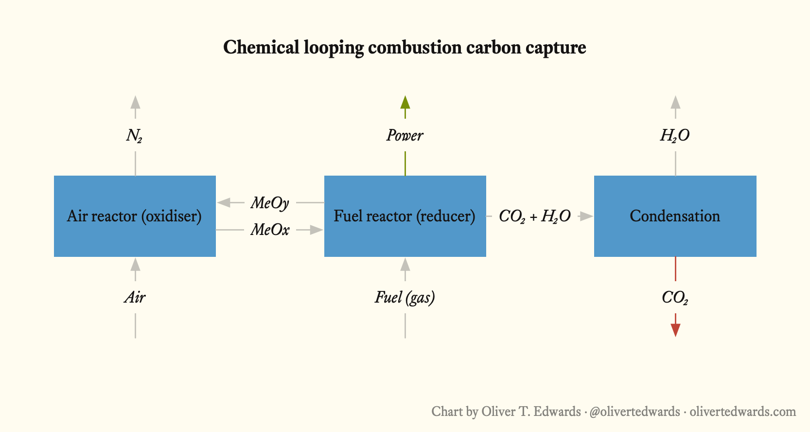
Chemical looping combustion
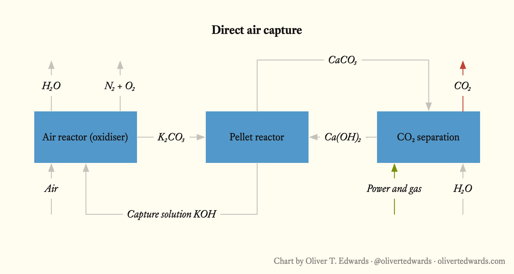
With chemical looping combustion (a novel concept also known as solid-looping) carbon capture methods, a solid oxygen carrier (for instance a metal oxide) transports oxygen from an air reactor to a separate fuel reactor, where it reacts with the fuel to produce CO₂ and water (Danish Energy Agency2024, pp.25). The oxygen carrier is reduced through the reaction, so it must be regenerated in a dedicated oxidising reactor with air. Like the oxy-fuel combustion method, this gives us a clean combustion environment without nitrogen, simplifying the CO₂ separation process, while removing the need for a dedicated air separation unit. With seemingly high efficiencies and lower costs with a directly integrated capture process, this method looks mostly relevant for gasification-based power plants or hydrogen facilities. Yet, the technology has only reached pilot scale and can’t be retrofitted onto existing industrial point sources.
Direct air capture
With direct air capture (DAC) methods, large fans pull ambient air through contactors where CO₂ can be absorbed by solvents or solid sorbents, then released as a concentrated stream through heating or other regeneration methods (Danish Energy Agency2024, pp.76). Given low atmospheric CO₂ concentrations (about 0.04%), this process is extremely energy-intensive because we need to move massive air volumes and the high temperature requirements for the reaction drive up costs. We’ve mostly seen smaller operational projects and demos, but there are some serious scaling and funding efforts going on. The biggest advantage is that you can place DAC plants anywhere, near renewable energy sources, carbon storage sites, or utilisation facilities where the facility can provide the CO₂ feedstock needed in e-fuel production, as well as carbon-negative outcomes when connected with permanent storage.
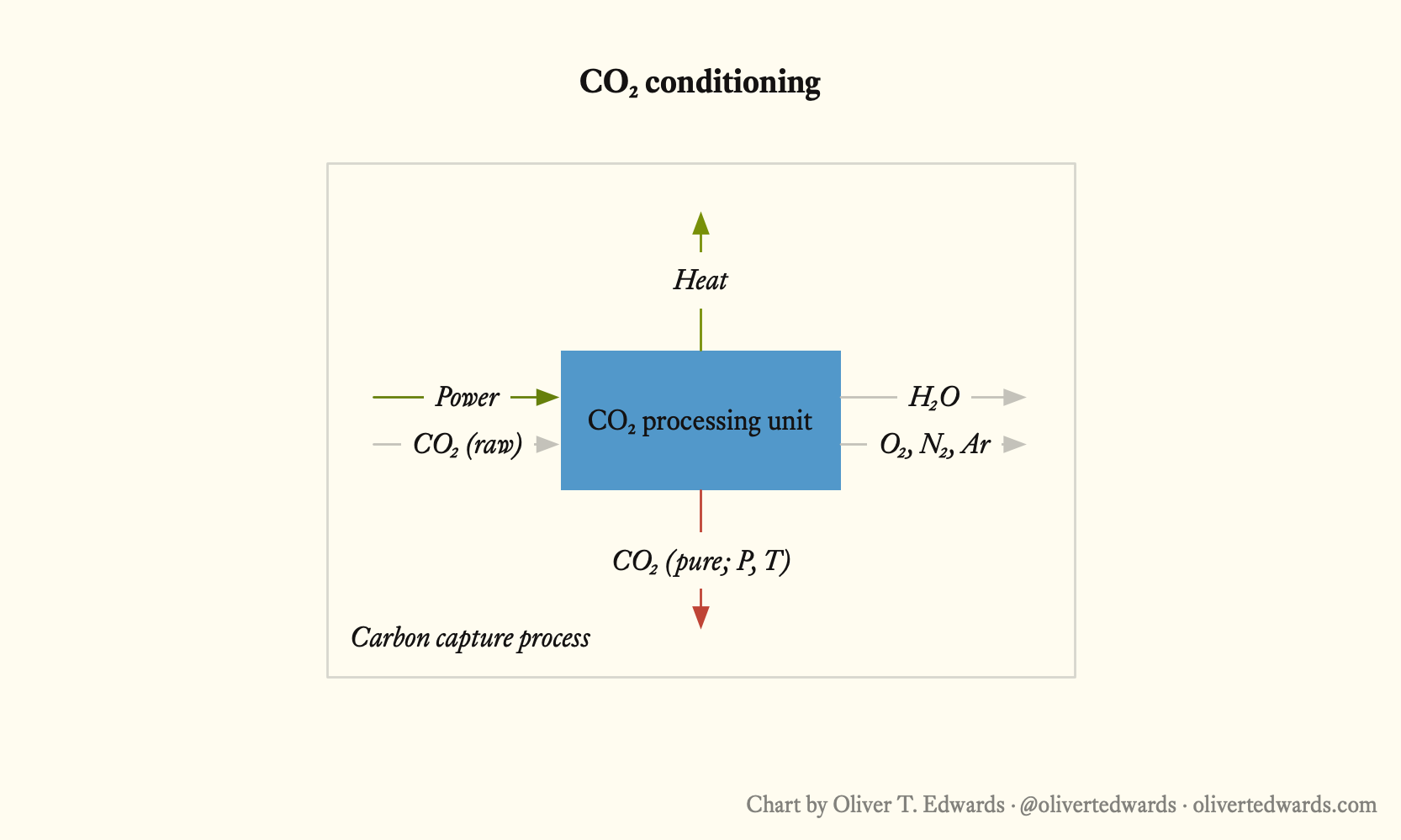
Post conditioning
Regardless of technology, CO₂ must be conditioned after capture to achieve the appropriate purity and state where it can be transported and stored safely in accordance with the remaining value chain. Depending on the emissions point source and capture method, captured CO₂ contains different impurities like water, sulfur compounds, and particulates that can corrode pipelines, storage equipment or disrupt injection into geological formations. Conditioning happens through a combination of dehydration, compression, and sometimes additional purification processes.
Technology selection
The five capture methods vary widely in maturity, retrofit potential, and fit for specific industrial processes. Understanding where each sits on these dimensions is more useful than TRL scores alone (Kearns2025, pp.7).
Retrofit versus greenfield is the first constraint. Post-combustion is the only method that can be added onto an existing exhaust stack without redesigning the underlying process. Pre-combustion and chemical looping require integration at the fuel-conversion stage, making them greenfield or major-modification propositions. Oxyfuel combustion sits in between: technically feasible as a retrofit in some cement or power applications, but rarely economic without significant facility modifications.
CO₂ concentration in the source stream drives cost more than any other single factor. Pre-combustion syngas streams carry 15–35% CO₂, making separation relatively straightforward. Post-combustion flue gases typically run at 3–15%. Direct air capture contends with atmospheric concentrations of roughly 0.04%, which is why its energy and cost penalties are so much larger. It is not a failure of the technology, but just the physics of working with highly diluted streams.
Heat availability matters most for absorption-based post-combustion systems, which consume 3–4 GJ per tonne of CO₂ in solvent regeneration. Facilities with excess low-value heat (combined heat and power plants, waste-to-energy, some refineries) can integrate this step efficiently. Facilities without it face a harder economics case unless grid power is both cheap and clean.
Industry-specific fits follow from the above. Cement kilns, where fuel and process emissions are mixed and temperatures are high, suit calcium looping or oxyfuel combustion. Steel blast furnaces lean toward post-combustion or chemical looping once the latter reaches commercial scale. Hydrogen production via steam methane reforming is a natural home for pre-combustion separation, since the syngas already requires CO₂ removal as part of the process. Power plants have the widest menu of options depending on fuel type and whether the facility is new-build or existing.
For most operators today, post-combustion amine absorption is the default answer. They are commercially proven, retrofittable, and supported by supply chains. The other methods are worth tracking closely, particularly for new-build industrial assets where integration costs can be designed in from the start rather than bolted on later.
Solution provider snapshot
Kearns2025 provides and excellent catalogue of over 70 commercially available and emerging carbon capture solutions, covering performance data, cost ranges, and commercial readiness indicators for each. The table below is a partial excerpt from that report organised by capture method; refer to the full report for the complete inventory. The TRLs reflect those assessed at the time of publication, and the report seems to be updated annually.
| Solution | Provider | Method | Target | TRL |
|---|---|---|---|---|
| 8RH₂ | 8 Rivers | Oxyfuel combustion | Hydrogen, ammonia/fertiliser, refining, transportation fuels, coal fuel switching, methanol, oxo-alcohols | 5 |
| AFC-C & Biome | 8 Rivers | Oxyfuel combustion | Power generation | 6 |
| Calcite | 8 Rivers | Direct air capture | Direct air capture | 6 |
| Flue gas amines | Air Liquide | Post combustion | SMR, boilers, fired heaters, waste incineration, refineries (FCC), BECCS, power plants, pulp and paper | 8-9 |
| Syngas amines | Air Liquide | Post combustion | H₂ production (SMR, POX, ATR), syngas with 15-35% CO₂, oxo-syngas with 3-15% CO₂ | 8-9 |
| Cryocap H₂ | Air Liquide | Post combustion | H₂ production (SMR or ATR) | 7-8 |
| Cryocap FG | Air Liquide | Post combustion | Flue gases or off-gases with CO₂ content >= 15% (SMR, cement/lime, steel blast furnace, refineries (FCC), waste incineration/biomass power plant, pulp & paper) | 7-8 |
| Cryocap Oxy | Air Liquide | Post combustion | Cement/lime, power plant, any applications with CO₂ concentration >50% | 7-8 |
| Cryocap Steel | Air Liquide | Post combustion | Iron and steel production | 7-8 |
| Cryocap LQ | Air Liquide | Conditioning | Liquefaction | 7 |
| Rectisol | Air Liquide | Pre combustion | NG-based low carbon H₂ or NH₃, biomass or MSW-based gasification for the production of SAFs, H₂, MeOH, NH₃, solid carbonaceous-based applications (IGCC, chemicals) | 9 |
| Recticap | Air Liquide | Pre combustion | Syngas bulk CO₂ removal for production of decarbonised hydrogen, ammonia/urea | 9 |
| DMX | Axens | Post combustion | Power generation, steel mills, refineries, waste incinerators, and chemical, cement, lime, glass, paper, aluminium production | 8 |
| Deoxygenation and dehydration | BASF | Conditioning | Treatment downstream of CO₂ capture technology | 9 |
| OASE White | BASF | Post combustion | Removes CO₂ and sulfur from process gases, especially in syngas and NG applications, ammonia, hydrogen | 9 |
| OASE Blue | BASF | Post combustion | Large-scale capture from flue gases, fossil power generation, waste incineration, cement | 9 |
| Chilled ammonia process | Baker Hughes | Post combustion | Fossil fuel-based power plants, waste to energy, biomass, cement, refineries, petrochemical complexes | 7 |
| Compact carbon capture | Baker Hughes | Post combustion | Fossil fuel-based power plants, waste to energy, biomass, cement, refineries, petrochemical complexes | 5 |
| Mixed-salt process | Baker Hughes | Post combustion | Waste to energy, biomass, industrial (cement), oil and gas (SMR, boilers) | 5 |
| CapsolEoP | Capsol Technologies | Post combustion | Full scale capture, cement, biomass, waste to energy, lime, pulp and paper, power generation, process industries. | 7-8 |
| CapsolGo | Capsol Technologies | Post combustion | Mobile demonstration unit for cement, biomass, waste to energy, lime | 7-8 |
| CapsolGT | Capsol Technologies | Post combustion | Gas turbines, low-carbon power plants | 6 |
| CycloneCC | Carbon Clean | Post combustion | Energy, industrial power, gas turbines, industrial emitters (cement, steel, waste to energy), maritime | 7-9 |
| Amine capture plant | China Energy | Post combustion | Large scale capture, power generation | 7 |
| CO₂ capture absorbent | CNPC | Post combustion | Power generation, cement, steel, petrochemicals | 9 |
| CO2SORB | CO2CRC | Post combustion,Pre combustion | High pressure (50 bar) capture from oil and gas, hydrogen operations | 4-5 |
| HyCaps | CO2CRC | Post combustion | Hybrid capture solution, power, industry, oil and gas, hard-to-abate sectors, small footprint operations (OCCS, remote/offshore platform) | 6-7 |
-
Technology readiness levels (TRL); a method for consistently estimating the maturity of technologies during the acquisition phase of a project on scale of 1-9 (9 is the most mature). Levels are determined in a technology readiness assessment (TRA) examining technology concepts, requirements, and demonstrated capabilities. ↩︎
-
Flue gas; a gas exiting to the atmosphere via a flue, a pipe/channel for conveying exhaust gases, as from a fireplace, oven, furnace, boiler or steam generator, often referring to the exhaust gas from a power plant. ↩︎
-
Absorption; the process in which atoms, molecules, or ions enter the bulk phase of a material, such as a liquid or solid. This differs from adsorption, where particles adhere to the surface of a material. ↩︎
-
Pressure swing adsorption (PSA); a method used to separate gases from a mixture based on their molecular characteristics and how strongly they adhere to an adsorbent material under pressure. This process operates at near-ambient temperatures and is commonly used to produce high-purity nitrogen or oxygen from air. ↩︎
Bibliography
-
Kearns2025 “State of the Art: CCS Technologies 2025”, Global CCS Insititute
Global CCS Institute compendium documenting over 70 commercially available and emerging carbon capture technologies, including post-combustion amine scrubbing, oxyfuel combustion, chemical looping, pre-combustion separation, and direct air capture, with performance data, cost ranges, and commercial readiness indicators for each. The report provides the most comprehensive single-volume technology survey currently available, useful both for benchmarking capture options at specific industrial facilities and for understanding where the technology frontier is — and where the gap between claimed performance and commercial reality remains wide.
-
Danish Energy Agency2024 “Technology Data for Carbon Capture, Transport and Storage”, Danish Energy Agency & Energinet
Technology catalogue published by the Danish Energy Agency and Energinet documenting commercially available and emerging solutions for carbon capture, CO₂ transport, and geological storage. The catalogue covers post-combustion capture, oxyfuel, pre-combustion, and direct air capture across thermal and industrial applications, alongside pipeline, ship, and rail transport options and a range of storage configurations. Its primary value is the cost and performance data it provides for benchmarking technology choices; the kind of reference that turns “we’ll figure out the details later” into a fundable project proposal.